Introduction
This information complements the SPN1 and BF5 Quick Start Guides and User Manuals. It gives a specific example of how to connect the SPN1 or BF5 to a DL2e logger. When used with a DL2e logging program the data provides hourly averages of Total and Diffuse radiation and the fraction of sun hours each hour.
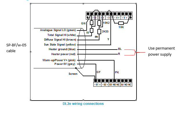
BF5 Wiring Schematic for the DL2e
See larger image in this link:
https://www.delta-t.co.uk/wp-content/uploads/2017/01/BF5-wiring.png

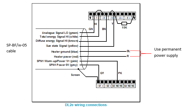
SPN1 Wiring Schematic for DL2e
See larger image in this link:
https://www.delta-t.co.uk/wp-content/uploads/2017/01/spn1-wiring2.png

DL2e Logger with LAC1
This diagram shows the wiring connections for the LAC1 analogue input card. For use with other cards, please refer to the DL2e Logger User Manual.
Settings
The example shows the SPN1/BF5 sensor outputs connected to analogue channels 1, 2 and 3 in the DL2e logger. Channel 1 DIP switches near the terminal connector must be set to the OFF (down) position.
The SPN1/BF5 is a powered sensor. All analogue outputs should be read using differential channels, for best noise avoidance.
The LAC1 input card of the DL2e logger is used in its 15-channel (differential) mode, with the 15-30 slider set to “15”. Power warm-up for the sensor is shown routed through relay channel 63. Power from the logger’s own battery is connected to terminal 63 using the internal jumper in the DL2e logger.
The cable screen is connected to channel 61- or 62- terminals for electrical screening purposes. These are the digital earth/frame connections of the DL2e, and are also used for the Power 0V return.
Special Considerations
Relay Warm-up for Powered Channels
The sensor needs a warm-up signal in order to enable the circuitry to produce the output signals. Specify one of the DL2e relay channels 63 or 64, and configure it for the warm-up function with a warm-up time of 1 second.
Total & Diffuse Outputs
The Total & Diffuse analogue outputs are shown connected to channels 1 and 2.
Sun State Output Options
The Sun state output is shown connected to analogue channel 3. This uses an analogue channel to produce sun hours data.
Analogue channel 3 is configured as a resistance channel (in the 3-wire mode). The precision 10kW resistor (0.1% tolerance) is a load resistor. If you cannot obtain this component locally, please request one from Delta-T tech support.
When the sun is present, the switch contact is closed. The load resistor is thus shorted to ground and the channel will read zero ohms.
With no sun, the switch contact open circuit, and the resistance reading is 10 kW. By means of special DL2e sensor codes these values can be recorded as sun hours in the logger data.
SPN1 Sensor Codes and Program for the DL2e
DL2e sensor codes for the SPN1 are included in the Ls2Win SR5 (or later) release. Please upgrade your PC installation first if it is an earlier service release version.
SPW
Use this code for the Total energy (W.m-2) and Diffuse energy (W.m-2) outputs from the SPN1.
SPD
Select this code for the sun state output connected to an analogue channel, using the precision 10kW load resistor (as in the diagram above). This will give readings in sun hours per day.
Warning! You must use this code only with a 24h average period.
You must start your logging run at the time at which you want your daily total logged (e.g. midnight, or 9 am).
SPH
Similar to SPD, but this will give readings in sun hours per hour.
Warning! You must use this code only with a 1h average period.
A sample DL2e logger program file (e.g. SPN1xmpl.pg2) which uses the SPW and SPH code is available from Delta-T.
BF5 Sensor Codes and Program for the DL2e
DL2e sensor codes for the BF5 are included in the Ls2Win SR7 (or later) release. Please upgrade your PC installation first if it is an earlier service release version.
BFP
Use this code for the Total PAR (mmol.m-2.s-1) and Diffuse PAR(mmol.m-2.s-1) outputs from the BF5. Note that it has a conversion factor of 0.8 to allow for the use of the resistor attenuator.
BFW
Use this code for the Total Energy (W.m-2) and Diffuse Energy (W.m-2) outputs from the BF5. Note that it has a conversion factor of 0.8 to allow for the use of the resistor attenuator.
BFL
Use this code for the Total Illuminance (klux) and Diffuse Illuminance (klux) outputs from the BF5. Note that it has a conversion factor of 0.8 to allow for the use of the resistor attenuator.
BFD
Select this code for the sun state output with an analog channel, using the precision 10kW load resistor (as in the diagram above). This will give readings in sun hours per day.
Warning! You must use this code only with a 24h average period.
You must start your logging run at the time at which you want your daily total logged (eg midnight, or 9 am).
Warning! If you occasionally get “noisy” readings reported by the DL2e, change the sensor code Autorange function (A) to Fixed Range (F) in the logger configuration.
BFH
Similar to BFD, but this will give readings in sun hours per hour.
Warning! You must use this code only with a 1h average period.
Connecting the Heater
Connect the heater wires to a suitable power supply. In air temperatures below 5°C the heater can consume 1.5A at 12V DC. For extended data logging in cold climates, we recommended that you power the heater via a 12 V supplypowered from the mains. Protect the heater power supply from moisture.
Take particular care to check that all ground and 0V connections to the various devices attached to the sensor at any time do not create earth-loops. Refer to the sensor user manual for further guidance on this issue.

