- Overview
- Specification
- Accessories
- Product Resources How to Buy
Testimonials
- Measures global and diffuse radiation
- Sunshine duration
- No moving parts, no shade rings
- PAR reference sensor for SunScan System
- Outputs can be PAR (mmol.m-2.s-1), Energy (W.m-2) or Lux
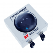
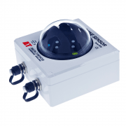
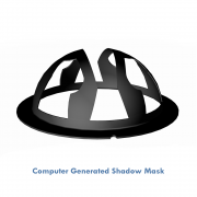
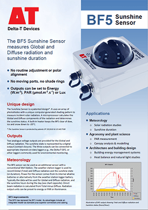
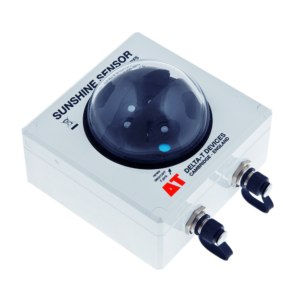
The BF5 Sunshine Sensor is a versatile, multi-purpose solar radiation sensor. It uses an array of photodiodes with a unique computer-generated shading pattern to measure incident solar radiation. A microprocessor calculates the global and diffuse components of the radiation and determines the sunshine state.
Two analogue voltage outputs give global and diffuse radiation, from which direct and diffuse radiation are derived. The sunshine state is indicated by a digital output. The three outputs can be connected to appropriate channels on the GP1 or GP2 data loggers, or other loggers commonly used for environmental monitoring. An internal heater keeps the BF5 Sunshine Sensor clear of dew, ice and snow down to -20 °C.
Sunshine Duration
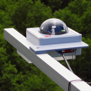
The BF5 Sunshine Sensor measures sunshine hours indirectly using a simple equation based on the total PAR radiation (Photosynthetically Active Radiation), and the ratio of total to direct PAR. This sunshine algorithm corresponds closely to the World Met Office threshold of 120 W/m-2 in the solar beam for sunshine duration. The BF5 Sunshine Sensor does not need to be adjusted or repositioned to track the sun – a distinct advantage over devices with shadow rings. There are no complex electro-mechanical assemblies and no burnt paper tracks to interpret.
SunScan Canopy Analysis System
The BF5 Sunshine Sensor can be used as an integral component of the SunScan Canopy Analysis system. The SunScan Probe is a 1 m long light sensor array suitable for measuring PAR interception by plant canopies and estimating LAI (Leaf Area Index). The BF5 Sunshine Sensor improves the accuracy of the SunScan system and enables it to be used even under variable light conditions.
Applications
In addition to its role in the SunScan System, the BF5 Sunshine Sensor’s alternative outputs enable it to be used in the study of photosynthesis, illumination and solar energy measurement.
For building energy management systems (BEMS), the BF5 can be used to control the opening and closing of blinds or louvres in response to sunlight. The BF5’s ability to measure both the energy in the direct beam and also total radiation, makes it possible to optimise the use of natural light and solar gain while minimising glare for the building’s occupants.
Comparison with SPN1 Sunshine Pyranometer
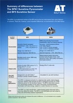
The SPN1 Sunshine Pyranometer is a precision version of the BF5 Sunshine Sensor and although the two instruments have some features in common, there are important differences. These are summarised in the document: “SPN1 and BF5 Comparison Data Sheet“.
REFERENCES: Wood J, Muneer T, Kubie J (Feb 2003), “Evaluation of a new photodiode sensor for measuring global and diffuse irradiance, and sunshine duration” Journal Solar Energy Engineering.
Specification
For simultaneous outputs of total radiation, diffuse radiation and sunshine status. Output can be pre-set to PAR, Energy or Lux units.
| Output setting | |||
| PAR | Energy | Illuminance | |
| Units | µmol.m-2.s-1 | W.m-2 | klux |
| Overall accuracy: Total | ±10 µmol.m-2.s-1 ±12% | ±5 W.m-2 ±12% | ±0.600 klux ±12% |
| Overall accuracy: Diffuse | ±10 µmol.m-2.s-1 ±15% | ±20 W.m-2 ±15% | ±0.600 klux ±15% |
| Resolution | 0.6 µmol.m-2.s-1 | 0.3 W.m-2 | 0.060 klux |
| Range | 0-2500 µmol.m-2.s-1 | 0-1250 W.m-2 | 0-200 klux |
| Analogue output sensitivity | 1 mV = 1 µmol.m-2.s-1 | 1 mV = 0.5 W.m-2 | 1 mV = 0.100 klux |
| Analogue output range | 0-2500 mV | 0-2500 mV | 0-2000 mV |
| Accuracy : Sunshine hours | ±10% compared to the WMO definition |
| Accuracy : Cosine correction | ±10% of incoming radiation over 0-90° Zenith angle |
| Accuracy : Azimuth angle | ± 5% over 360° rotation |
| Temperature coefficient | ± 0.15 % /°C (typical) |
| Temperature range | -20 to + 50°C with Alkaline batteries -20 to + 70°C with Lithium batteries |
| Stability | Recalibration recommended every 2 years. |
| Response time | < 250 ms |
| Spectral response | 400-700 nm |
| Latitude capability | -90° to + 90° |
| Environmental | IP65 ( shower and dust proof) |
| Sunshine status : contact closure | No sun = open circuit Sun = short circuit to ground |
| Internal battery | 2 x 1.5 V AA alkaline batteries |
| Power requirement | 2 mA (awake ), <30 µA (asleep) |
| Heater power | 12 V – 15 VDC, up to 1.5 A |
| Battery lifetime | 1 year (typical) |
| Input voltage range – powered from internal battery | 1.4 to 3.6 VDC |
| Input voltage range – external power | 5 to 15 VDC |
| Fuse trip point, on sunshine status signal, (when in switch-closure mode) | 0.5 A, 30 V (self-resetting) |
| Max applied voltage to sunshine status output, in contact closure mode | 0 to 24 V |
| RS232 connector | 5-pin M12 |
| Signal output & power-in connector | 8 pin M12 |
| Mounting options: | Camera tripod socket (¼ inch Whitworth). Holes for 4 x M4 bolts at corners of box. |
| Size & Weight | 120 mm x 122 mm x 95 mm, 635 g |
Accessories
Hardware
Main components and software
Mountings and enclosures
Installation accessories
Cables and networks
Remote communications
Spares and consumables
Power options
Other
Product Resources
Data Sheets
Case Studies
-
Greenwich University uses BF5 in greenhouse solar panel research 1 MBFilename: BF5_Greenwich_University_Case_Study_version_1
Software
Manuals
FAQs
-
Why are my solar radiation readings higher than the solar constant? (SPN1, BF5, GS2-05)
Question
Why are my solar radiation readings higher than the solar constant? (SPN1, BF5, GS2-05)
Answer
Sometimes, during the day, the sensor may read higher than the solar constant (greater than ~1370W.m-2)
This is something that has been seen in rare, isolated conditions. This can usually be caused by:- Certain types of cloud cover magnifying the sun’s rays and increasing the irradiance. This tends to be when cloud cover is sporadic and the sunshine is intermittently broken up as the clouds pass by.
- Water on the dome/sensing diffuser, again magnifying the irradiance seen by the sensor.
- A nearby reflective object shining onto the sensor (this should be noticed at a similar time of day, every day during the same season).
These events are extreme and of short duration. They also tend to get lost if you only keep averages of the series (e.g. 1 minute samples logged every hour).
-
How do you insert large diameter cables (e.g. SPN1/BF5 cables) into the GP1/GP2/DL6 cable glands? – Video Guide
Question
How do you insert large diameter cables (e.g. SPN1/BF5 cables) into the GP1/DL6 cable glands? - Video Guide
Answer
The following video explains the best way that this can be done:
https://www.dropbox.com/s/lx9oyan70i75sgu/8%20way%20cable%20with%20sound.wmv?dl=0
Example in video is 8-way BF5 cable and GP1.
The GP2 logger has an optional expansion lid (GP2-G5-LID), which contains larger cable gland sizes to help with large diameter cables.
-
How do I wire my BF5/SPN1 up to a DL2e Data logger?
Question
How do I wire my BF5/SPN1 up to a DL2e Data logger?
Answer
Introduction
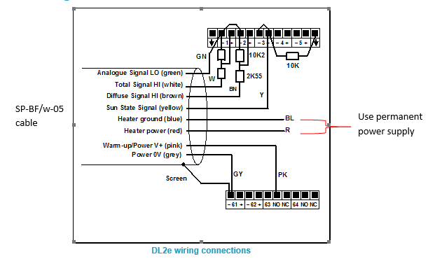
This information complements the SPN1 and BF5 Quick Start Guides and User Manuals. It gives a specific example of how to connect the SPN1 or BF5 to a DL2e logger. When used with a DL2e logging program the data provides hourly averages of Total and Diffuse radiation and the fraction of sun hours each hour.BF5 Wiring Schematic for the DL2e
See larger image in this link:
https://www.delta-t.co.uk/wp-content/uploads/2017/01/BF5-wiring.png
SPN1 Wiring Schematic for DL2e
See larger image in this link:
https://www.delta-t.co.uk/wp-content/uploads/2017/01/spn1-wiring2.png
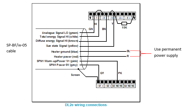
DL2e Logger with LAC1
This diagram shows the wiring connections for the LAC1 analogue input card. For use with other cards, please refer to the DL2e Logger User Manual.
Settings
The example shows the SPN1/BF5 sensor outputs connected to analogue channels 1, 2 and 3 in the DL2e logger. Channel 1 DIP switches near the terminal connector must be set to the OFF (down) position.
The SPN1/BF5 is a powered sensor. All analogue outputs should be read using differential channels, for best noise avoidance.
The LAC1 input card of the DL2e logger is used in its 15-channel (differential) mode, with the 15-30 slider set to “15”. Power warm-up for the sensor is shown routed through relay channel 63. Power from the logger’s own battery is connected to terminal 63 using the internal jumper in the DL2e logger.
The cable screen is connected to channel 61- or 62- terminals for electrical screening purposes. These are the digital earth/frame connections of the DL2e, and are also used for the Power 0V return.Special Considerations
Relay Warm-up for Powered Channels
The sensor needs a warm-up signal in order to enable the circuitry to produce the output signals. Specify one of the DL2e relay channels 63 or 64, and configure it for the warm-up function with a warm-up time of 1 second.Total & Diffuse Outputs
The Total & Diffuse analogue outputs are shown connected to channels 1 and 2.Sun State Output Options
The Sun state output is shown connected to analogue channel 3. This uses an analogue channel to produce sun hours data.
Analogue channel 3 is configured as a resistance channel (in the 3-wire mode). The precision 10kW resistor (0.1% tolerance) is a load resistor. If you cannot obtain this component locally, please request one from Delta-T tech support.
When the sun is present, the switch contact is closed. The load resistor is thus shorted to ground and the channel will read zero ohms.
With no sun, the switch contact open circuit, and the resistance reading is 10 kW. By means of special DL2e sensor codes these values can be recorded as sun hours in the logger data.SPN1 Sensor Codes and Program for the DL2e
DL2e sensor codes for the SPN1 are included in the Ls2Win SR5 (or later) release. Please upgrade your PC installation first if it is an earlier service release version.
SPW
Use this code for the Total energy (W.m-2) and Diffuse energy (W.m-2) outputs from the SPN1.SPD
Select this code for the sun state output connected to an analogue channel, using the precision 10kW load resistor (as in the diagram above). This will give readings in sun hours per day.Warning! You must use this code only with a 24h average period.
You must start your logging run at the time at which you want your daily total logged (e.g. midnight, or 9 am).
SPH
Similar to SPD, but this will give readings in sun hours per hour.
Warning! You must use this code only with a 1h average period.
A sample DL2e logger program file (e.g. SPN1xmpl.pg2) which uses the SPW and SPH code is available from Delta-T.BF5 Sensor Codes and Program for the DL2e
DL2e sensor codes for the BF5 are included in the Ls2Win SR7 (or later) release. Please upgrade your PC installation first if it is an earlier service release version.
BFP
Use this code for the Total PAR (mmol.m-2.s-1) and Diffuse PAR(mmol.m-2.s-1) outputs from the BF5. Note that it has a conversion factor of 0.8 to allow for the use of the resistor attenuator.BFW
Use this code for the Total Energy (W.m-2) and Diffuse Energy (W.m-2) outputs from the BF5. Note that it has a conversion factor of 0.8 to allow for the use of the resistor attenuator.BFL
Use this code for the Total Illuminance (klux) and Diffuse Illuminance (klux) outputs from the BF5. Note that it has a conversion factor of 0.8 to allow for the use of the resistor attenuator.BFD
Select this code for the sun state output with an analog channel, using the precision 10kW load resistor (as in the diagram above). This will give readings in sun hours per day.
Warning! You must use this code only with a 24h average period.
You must start your logging run at the time at which you want your daily total logged (eg midnight, or 9 am).
Warning! If you occasionally get “noisy” readings reported by the DL2e, change the sensor code Autorange function (A) to Fixed Range (F) in the logger configuration.BFH
Similar to BFD, but this will give readings in sun hours per hour.
Warning! You must use this code only with a 1h average period.Connecting the Heater
Connect the heater wires to a suitable power supply. In air temperatures below 5°C the heater can consume 1.5A at 12V DC. For extended data logging in cold climates, we recommended that you power the heater via a 12 V supplypowered from the mains. Protect the heater power supply from moisture.
Take particular care to check that all ground and 0V connections to the various devices attached to the sensor at any time do not create earth-loops. Refer to the sensor user manual for further guidance on this issue. -
How do I set up my USB to RS232 convertor? – Photo Guide
Question
How do I set up my USB to RS232 convertor? - Photo Guide
Answer
- These convertors usually come with a website link to visit and download the drivers. Please make sure you download the drivers. Then follow all the on-screen instructions correctly.
- If you have purchased the device from Delta-T, you can download the drivers from here: https://www.dropbox.com/s/2pu0ll8b26y8qkm/CDM212364_Setup.exe?dl=0 or here: https://ftdichip.com/drivers/vcp-drivers/
- Once the drivers have been installed correctly, plug the USB convertor into a USB port on your PC.
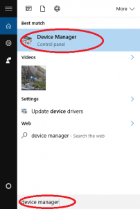
- The computer will then assign the convertor a COM port. You will need to check which com port has been assigned via the computer’s “device manager”:
Windows 10
Use the search tool in the bottom task bar to search for ‘device manager’:
Windows 8
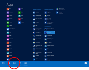
Right click on Desktop background and select ‘All Apps’Right click on control panel and select ‘properties’:
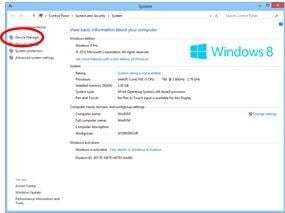
Click on Device Manager:
Windows 7
Click on Start, Control Panel, Device Manager:
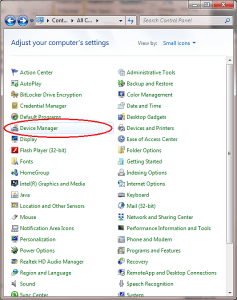
XP
Click on Start, Control Panel, System:
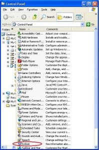
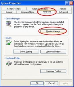
Under the ‘Hardware’ tab, click on ‘Device Manager’:
- Once in the device manager, expand the “ports” option. The example below shows a P.C which has the USB to serial converter installed (COM3):
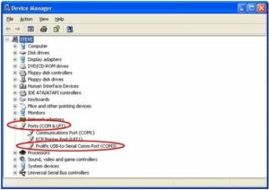
- Please make sure that you use this same COM port number in the device software e.g. HH2read, SunRead, LS2win, DeltaLINK, AP4 retrieve.
- You will probably have to re-boot the P.C once the drivers have been installed.
- Also, please remember to use the original RS232 cable, that was supplied with your device, in series with the RS232 to USB converter.
Multiple USB convertor Installations check
If you have more than one USB to RS232 convertor installed, you can check which COM port has been assigned to the one you want to use, by doing the following:
- Unplug the USB convertor
- Open Device Manager > Ports (COM & LPT)
- Plug in the USB connector and observe which COM port is added to the list.
Technical Notes
Product Comparisons
- SPN1 Pyranometer Performance including BF5 / SPN1 Comparison
Comparison of SPN1 Sunshine Pyranometer with WMO and ISO pyranometer standards. Also compares the main differences between the SPN1 Sunshine Pyranometer and the BF5 Sunshine Sensor.
DownloadFilename: spn1_perf_and_bf5_comp_v1


