- Overview
- Specification
- Accessories
- Product Resources How to Buy
DISCONTINUED PRODUCT
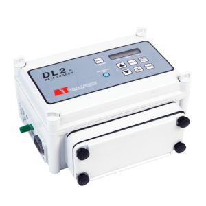
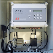
The DL2e Data Logger was manufactured by Delta-T Devices from 1986 to 2019 but has now been discontinued. Its reliability and flexibility made it a popular choice with customers, and we know that large numbers are still in use.
We would like to reassure users that Delta-T will continue to provide technical support and repairs for the DL2e for many years to come. Repairs Calibration and Warranty
The DL2e has been replaced by the GP2 Data Logger.
Specification
DISCONTINUED PRODUCT| Input connections | 15 analog channels expandable to 30, 45,or 60 |
| 2 counters | |
| Control outputs | 2 relays (1A) |
| Readings stored | 128,000 |
| Recording rate | 1 second to 24 hours |
| Configuration | Ls2Win |
| Communication options | RS232, USB [1] |
| Sensor excitation | 2 relay switched logger or external power |
| Power | 6 AA alkaline batteries or external power 7-15V |
| Battery life (dependent on usage) | ~ 6 months |
| Enclosure rating | IP65 |
| Temperature range | -20 to +60°C |
| Display | 2 line x 16 character |
| Size | 280 x 220 x 140mm |
| Typical applications | General data logging for moderate to complex systems |
| Sensor compatibility (maximum number of sensors that could be connected [2] | |
| ML3 | ✓ (30) with temp / (60) without temp |
| SM150T | ✓ (30) with temp / (60) without temp |
| PR2 | ✓ (10 PR2/6) (15 PR2/4) |
| PR2 SDI-12 | – |
| WET Sensor | – |
| EQ3 | ✓(30) with temp / (60) without temp |
| Temperature | ✓(60) |
| Tensiometers | ✓(60), requires TVB1s |
| Counters or Events | ✓(2) |
| Relay Output | ✓(2) |
[1] With USB to RS232 Adapter Cable type USB-RS232
[2] With appropriate expansion cards and power supply arrangements
For full DL2e specification please see the DL2e data sheet
Accessories
Hardware
Main components and software
Mountings and enclosures
Installation accessories
Cables and networks
Remote communications
Spares and consumables
Power options
Other
Product Resources
Software
Manuals
- DL2e Data Logger Quick Start Guide v2.1 814 KB
This document covers the main functions and operations of the DL2e Logger and includes a tutorial section.
Filename: DL2e_Quick_Start_Guide_v2.1 - DL2e Hardware Reference v3. 15 Dec 2000. Document Code: DL2-UM-05-03 2 MB
Complete hardware reference manual for the DL2e. It also contains general guidance on the scope and application of the measurement techniques supported by the logger.
Filename: dl2e-data-logger-hardware-reference-tm - DL2e User Manual - Getting Started, v5.0, 2001. 1,023 KB
User Manual for DL2e Data Logger Getting Started, v5.0, 18 Jan 2001. Document Code: DL2-UM-04-05 Obsolete document. This manual has been replaced by the DL2e Data Logger Quick Start Guide which covers the same areas but has updated material.
Filename: dl2e-data-logger-getting-started-um - M Enclosure for DL2e Manual 2 MBFilename: m-encl-b-for-dl2e-v4-0
FAQs
-
Are there simple protocol commands to communicate with the Delta-T Devices Data loggers, so I can set up my own test software to communicate with them?
Question
Are there simple protocol commands to communicate with the Delta-T Devices Data loggers, so I can set up my own test software to communicate with them?
Answer
GP1, GP2 and DL6
The GP1/GP2 and DL6 loggers have a binary communications protocol, so it isn’t possible to use an ASCII terminal to communicate with them. We don’t publish the protocol because it’s highly optimized and complex, and it’s not practical for us to support development of custom implementations. Instead we provide a software development kit (SDK) for developing applications in Visual Studio, and a command line program for use in batch files for automating data retrieval.
- Using the development toolkit:
Instructions:
SDK instructions
Software can be found here:
link to software - Using a command line retrieval file to automatically retrieve a data file:
command line document link
DL2e
The DL2e does have a protocol for RS232 commands and the programmer’s guide can be found here:
DL2e programmer's guide - Using the development toolkit:
-
How do I apply a Leap year timestamp workaround for the DL2e Data Logger?
Question
How do I apply a Leap year timestamp workaround for the DL2e Data Logger?
Answer
This issue applies only to the DL2e logger. It is mentioned in the DL2e Hardware Manual p18. The DL2e has never had the year capability in its time-stamp, only day+month. In leap years, when there is a February 29 date, some action may be needed if the logging period extends beyond February 28 into March. The following notes explain what to do.
There are two possible problems:
- The DL2e datafile may not contain the February 29 date.
- The DL2e logger will report the date wrongly (by one day) until it is corrected.
The solutions are:
- Always use the Delta-T Dataset Import Wizard in Excel to import data from DL2e datafiles that cross a February 29 leap year date.
In the Dataset Import Wizard the user is asked to supply the year that the data in the .DAT (or .BIN) file applies to. It then provides this information to Excel so the resulting Excel file has all dates either side of February 29th automatically corrected where necessary.
Note: that this will NOT happen if the .DAT file is imported into Excel simply as a .CSV file. The user will then manually have to correct the dates after February 28. - If you want the DL2e to report the correct date then, at some convenient time on or after March 1st, download the data from the DL2e as above.
-
How do I wire my BF5/SPN1 up to a DL2e Data logger?
Question
How do I wire my BF5/SPN1 up to a DL2e Data logger?
Answer
Introduction
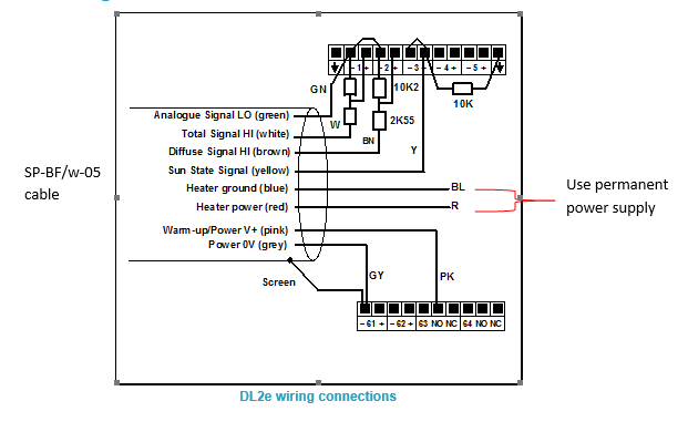
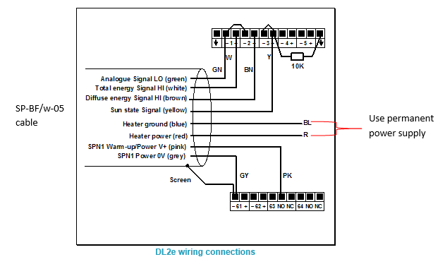
This information complements the SPN1 and BF5 Quick Start Guides and User Manuals. It gives a specific example of how to connect the SPN1 or BF5 to a DL2e logger. When used with a DL2e logging program the data provides hourly averages of Total and Diffuse radiation and the fraction of sun hours each hour.BF5 Wiring Schematic for the DL2e
See larger image in this link:
https://www.delta-t.co.uk/wp-content/uploads/2017/01/BF5-wiring.png
SPN1 Wiring Schematic for DL2e
See larger image in this link:
https://www.delta-t.co.uk/wp-content/uploads/2017/01/spn1-wiring2.png
DL2e Logger with LAC1
This diagram shows the wiring connections for the LAC1 analogue input card. For use with other cards, please refer to the DL2e Logger User Manual.
Settings
The example shows the SPN1/BF5 sensor outputs connected to analogue channels 1, 2 and 3 in the DL2e logger. Channel 1 DIP switches near the terminal connector must be set to the OFF (down) position.
The SPN1/BF5 is a powered sensor. All analogue outputs should be read using differential channels, for best noise avoidance.
The LAC1 input card of the DL2e logger is used in its 15-channel (differential) mode, with the 15-30 slider set to “15”. Power warm-up for the sensor is shown routed through relay channel 63. Power from the logger’s own battery is connected to terminal 63 using the internal jumper in the DL2e logger.
The cable screen is connected to channel 61- or 62- terminals for electrical screening purposes. These are the digital earth/frame connections of the DL2e, and are also used for the Power 0V return.Special Considerations
Relay Warm-up for Powered Channels
The sensor needs a warm-up signal in order to enable the circuitry to produce the output signals. Specify one of the DL2e relay channels 63 or 64, and configure it for the warm-up function with a warm-up time of 1 second.Total & Diffuse Outputs
The Total & Diffuse analogue outputs are shown connected to channels 1 and 2.Sun State Output Options
The Sun state output is shown connected to analogue channel 3. This uses an analogue channel to produce sun hours data.
Analogue channel 3 is configured as a resistance channel (in the 3-wire mode). The precision 10kW resistor (0.1% tolerance) is a load resistor. If you cannot obtain this component locally, please request one from Delta-T tech support.
When the sun is present, the switch contact is closed. The load resistor is thus shorted to ground and the channel will read zero ohms.
With no sun, the switch contact open circuit, and the resistance reading is 10 kW. By means of special DL2e sensor codes these values can be recorded as sun hours in the logger data.SPN1 Sensor Codes and Program for the DL2e
DL2e sensor codes for the SPN1 are included in the Ls2Win SR5 (or later) release. Please upgrade your PC installation first if it is an earlier service release version.
SPW
Use this code for the Total energy (W.m-2) and Diffuse energy (W.m-2) outputs from the SPN1.SPD
Select this code for the sun state output connected to an analogue channel, using the precision 10kW load resistor (as in the diagram above). This will give readings in sun hours per day.Warning! You must use this code only with a 24h average period.
You must start your logging run at the time at which you want your daily total logged (e.g. midnight, or 9 am).
SPH
Similar to SPD, but this will give readings in sun hours per hour.
Warning! You must use this code only with a 1h average period.
A sample DL2e logger program file (e.g. SPN1xmpl.pg2) which uses the SPW and SPH code is available from Delta-T.BF5 Sensor Codes and Program for the DL2e
DL2e sensor codes for the BF5 are included in the Ls2Win SR7 (or later) release. Please upgrade your PC installation first if it is an earlier service release version.
BFP
Use this code for the Total PAR (mmol.m-2.s-1) and Diffuse PAR(mmol.m-2.s-1) outputs from the BF5. Note that it has a conversion factor of 0.8 to allow for the use of the resistor attenuator.BFW
Use this code for the Total Energy (W.m-2) and Diffuse Energy (W.m-2) outputs from the BF5. Note that it has a conversion factor of 0.8 to allow for the use of the resistor attenuator.BFL
Use this code for the Total Illuminance (klux) and Diffuse Illuminance (klux) outputs from the BF5. Note that it has a conversion factor of 0.8 to allow for the use of the resistor attenuator.BFD
Select this code for the sun state output with an analog channel, using the precision 10kW load resistor (as in the diagram above). This will give readings in sun hours per day.
Warning! You must use this code only with a 24h average period.
You must start your logging run at the time at which you want your daily total logged (eg midnight, or 9 am).
Warning! If you occasionally get “noisy” readings reported by the DL2e, change the sensor code Autorange function (A) to Fixed Range (F) in the logger configuration.BFH
Similar to BFD, but this will give readings in sun hours per hour.
Warning! You must use this code only with a 1h average period.Connecting the Heater
Connect the heater wires to a suitable power supply. In air temperatures below 5°C the heater can consume 1.5A at 12V DC. For extended data logging in cold climates, we recommended that you power the heater via a 12 V supplypowered from the mains. Protect the heater power supply from moisture.
Take particular care to check that all ground and 0V connections to the various devices attached to the sensor at any time do not create earth-loops. Refer to the sensor user manual for further guidance on this issue. -
How do I set up my USB to RS232 convertor? – Photo Guide
Question
How do I set up my USB to RS232 convertor? - Photo Guide
Answer
- These convertors usually come with a website link to visit and download the drivers. Please make sure you download the drivers. Then follow all the on-screen instructions correctly.
- If you have purchased the device from Delta-T, you can download the drivers from here: https://www.dropbox.com/s/2pu0ll8b26y8qkm/CDM212364_Setup.exe?dl=0 or here: https://ftdichip.com/drivers/vcp-drivers/
- Once the drivers have been installed correctly, plug the USB convertor into a USB port on your PC.
- The computer will then assign the convertor a COM port. You will need to check which com port has been assigned via the computer’s “device manager”:
Windows 10
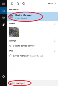
Use the search tool in the bottom task bar to search for ‘device manager’:
Windows 8
Right click on Desktop background and select ‘All Apps’Right click on control panel and select ‘properties’:
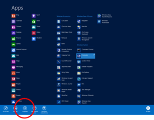
Click on Device Manager:
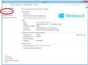
Windows 7
Click on Start, Control Panel, Device Manager:
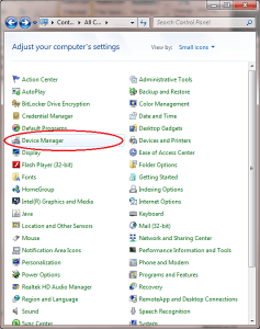
XP
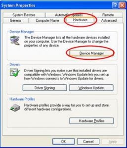
Click on Start, Control Panel, System:
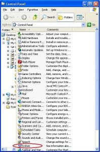
Under the ‘Hardware’ tab, click on ‘Device Manager’:
- Once in the device manager, expand the “ports” option. The example below shows a P.C which has the USB to serial converter installed (COM3):
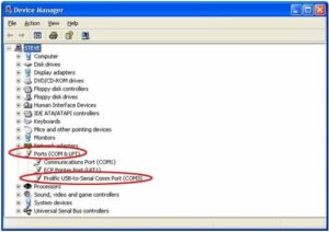
- Please make sure that you use this same COM port number in the device software e.g. HH2read, SunRead, LS2win, DeltaLINK, AP4 retrieve.
- You will probably have to re-boot the P.C once the drivers have been installed.
- Also, please remember to use the original RS232 cable, that was supplied with your device, in series with the RS232 to USB converter.
Multiple USB convertor Installations check
If you have more than one USB to RS232 convertor installed, you can check which COM port has been assigned to the one you want to use, by doing the following:
- Unplug the USB convertor
- Open Device Manager > Ports (COM & LPT)
- Plug in the USB connector and observe which COM port is added to the list.
Regulatory Information
- DL2e Logger EC Declaration of ConformityDownloadFilename: DL2e Data Logger


