- Overview
- Specification
- Accessories
- Product Resources How to Buy
- High accuracy 7 channel data logger
- 600,000 readings
- Free use of DeltaLINK-Cloud data sharing service
- Smart relay control
DeltaLINK–Cloud – free online data service
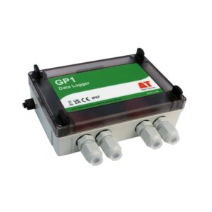
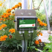
The GP1 Data Logger is a complete logging solution housed in a waterproof IP67 enclosure with battery power. The internal memory can hold >600,000 readings – more than enough for one year’s operation (typical).
The GP1 can log up to:
- 2 differential analogue voltages
- 2 temperature channels
- 2 pulse counters
As well as being a powerful general purpose logger, the GP1 is ideal for soil moisture applications and can log:
- 2 soil moisture sensors e.g. ThetaProbes or SM150Ts
- 2 temperature probes
- 2 pulse counters (e.g. rainfall or water meter)
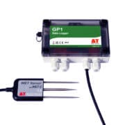
- 1 WET Sensor
The optional GP-PBA-X50 Precision Bridge Adapter enables a GP1 to log up to 2 bridge sensors such as pressure transducers and strain gauges.
When connected to 1 or 2 ThetaProbes or SM150T Soil Moisture Sensors, the GP1 Logger provides simple high accuracy recording of moisture content (as well as rainfall and temperature).
Irrigation control
The GP1 Data Logger, running DeltaLINK Software, can control irrigation directly from the soil moisture (and/or rainfall and/or temperature) or act as a sophisticated interface between these sensors and many types of programmable timer.
Start and Stop control levels can be separately configured and there’s even an option for pulsing the output when it’s desirable to match the water application rate to the soil’s infiltration capacity.
NB: Our GP2 Advanced Data logger and Controller offers even more advanced irrigation control capabilities.
DeltaLINK PC Software
DeltaLINK PC Software is supplied free with all GP1, GP2 and DL6 data loggers. DeltaLINK allows you to set up the logger input channels and recording parameters, check readings from connected sensors, and collect & display data.
- Clear graphic display
- Full configuration
Storage, communications and power
1 MB of FLASH memory enables storage of 600K readings (typical). Data can be collected by a laptop locally via RS232 or via USB (USB to RS232 Adaptor Cable type USB-RS232 required), or remotely using the cellular modem options.
The GP1 has 1 PP3 internal battery as standard. Up to 10 GP1s can share power and communications using an M8 cabling network. GP2 Data Loggers can be integrated into such a network via an adapter cable.
Applications
Soil Science, Plant Physiology, Agronomy, Climate Research and Meteorology
Horticulture, Agriculture, Turf and Gardens-Amenity Landscaping
Specification
| Input connections | 2 voltage channels |
| 2 temperatures or 2 additional SM150T Sensors [3] | |
| 2 counters (33 kHz & 50 Hz) | |
| 1 WET Sensor | |
| Control outputs | 1 relay (1 A) |
| Readings stored | 600,000 |
| Recording rate | 1 second to 24 hours |
| Configuration | DeltaLINK |
| Communication options | RS232 USB [1] or modem |
| Sensor excitation | 1 switched logger power 15 V precision reference |
| Power | 9 V 6LR61 (PP3) alkaline or external power 11-24 V |
| Battery life (dependent on usage) | >76k readings lasting >130 days |
| Enclosure rating | IP67 |
| Temperature range | -20 to +60°C |
| Display | – |
| Size | 140 x 105 x 45 mm |
| Typical applications | Monitoring soil moisture |
| General data logging | |
| Controlling irrigation |
| Sensor compatibility (maximum number of sensors that could be connected [2] | |
| ML3 | ✓ (2) with temp ✓ (4) excl. temp [3] |
| SM150T | ✓ (2) with temp ✓ (4) excl. temp [3] |
| PR2 | – |
| PR2 SDI-12 | – |
| WET Sensor | ✓(1) |
| EQ3 | ✓(2 as mV only) |
| Temperature | ✓(2) |
| Tensiometers (bridge sensors) | ✓(2) each requires GP-PBA-X50 |
| Counters or Events | ✓(2) 1 fast 1 slow |
| Relay Output | ✓(1) |
[1] With USB to RS232 Adapter Cable type USB-RS232
[2] With appropriate expansion cards and power supply arrangements
[3] Temperature channels provide only single-ended inputs so should not be used with long cables or in noisy environments when used with soil moisture sensors. The accuracy figures quoted for GP1 soil moisture readings do not apply to these resistance channels when configured as soil moisture inputs.
For full GP1 specification please see the GP1 data sheet or Quick Start Guide
Accessories
Hardware
Main components and software
Mountings and enclosures
Installation accessories
Cables and networks
Remote communications
Spares and consumables
Power options
Other
Product Resources
Data Sheets
- GP1 Data Logger Data Sheet 2 MB
- WS-GP1 Weather Station Data Sheet 1 MB
- DeltaLINK-Cloud - online data viewing and sharing service 2 MB
- Environmental and Meteorological Sensor Specifications 5 MB
- WS-GP1 Weather Station - Quick Slide Show 1 MB
Case Studies
-
Seven brief Delta-T Devices soil moisture measurement case studiesFilename: →
Manuals
- GP1 & DL6 Network QSG 1,007 KB
Installation instructions and pictorial guide to the components needed for connecting multiple loggers on a GP1/DL6 Cabling Network. Up to 10 GP1 or DL6 loggers may be networked. DeltaLINK v2.2 and GP1/DL6 firmware v1.30 (or later) are required
Filename: gp1-dl6-network-qsg-v1 - GP1 Logger Quick Start Guide v4.0 737 KBFilename: GP1_Quick_Start_Guide_v4.0
- 3G Modem Gateway User Manual v1.2 2 MBFilename: 3G_Modem_Gateway_User_Manual_v1.2
- GPRS Modem Gateway User Manual v1.1 2 MBFilename: gprs_modem_gateway-user_manual_v1-1
- GPRS Modem User Manual 3 MBFilename: gprs-modem-user-manual-v3
- Irrigation Control Quick Start Guide 796 KB
Explains how to adapt timer-based irrigation control systems to include soil moisture sensing using the GP1 irrigation monitor and SM300 Soil Moisture sensor.
Filename: irrigation-control-quick-start-guide - M2-TRPD Assembly Instructions 231 KBFilename: m2-trpd-assembly-instructions-v1-0
- WET-GP1 Logging Quick Start Guide v1.2 1 MB
Quick Start Guide describing how to use a WET sensor with a GP1 logger.
Filename: wet-gp1-logging-v1-2 - WS-GP1 Weather Station Quick Start Guide 2 MB
Quick Start Guide for the pre-wired and pre-programmed WS-GP1 Weather Station v1.0. Contents: unpacking, location. assembly, orientation, programming, data collection and graphing, specifications and service. 12 page A5 colour booklet with 26 illustrations.
Filename: ws-gp1-weather-station-qsg
FAQs
-
What checks are needed when setting up a DeltaLINK-Cloud modem gateway after a period of storage?
Question
What checks are needed when setting up a DeltaLINK-Cloud modem gateway after a period of storage?
Answer
You may choose to shut down your DeltaLINK-Cloud modem once the growing season is over (e.g. Winter). When setting up the equipment again for the next growing season, it’s important to perform a few checks, just to make sure everything is working ok.
-
- Re-charge the 12v battery before redeploying otherwise the modem won’t have any power to start up. If you need a battery charger for the LBAT4 battery, please contact sales@delta-t.co.uk.
- Make sure the aerial/antenna is connected securely and is mounted as high as possible.
- Make sure all loggers are connected to the modem box/kit. Check the cables for any damage that may have occurred during storage. If replacement cables are needed, please contact sales@delta-t.co.uk.
- Connect the 12v battery to the power leads in the modem box or, if you are using the kit in a steel enclosure, make sure the battery is connected directly into the logger power terminals and the modem is connected to the logger using the 5-way M12 connector.
- Check the modem status LED (note, the modem may take a few minutes to connect to the network and display the correct LED flashing code):
2G FX009 modem:
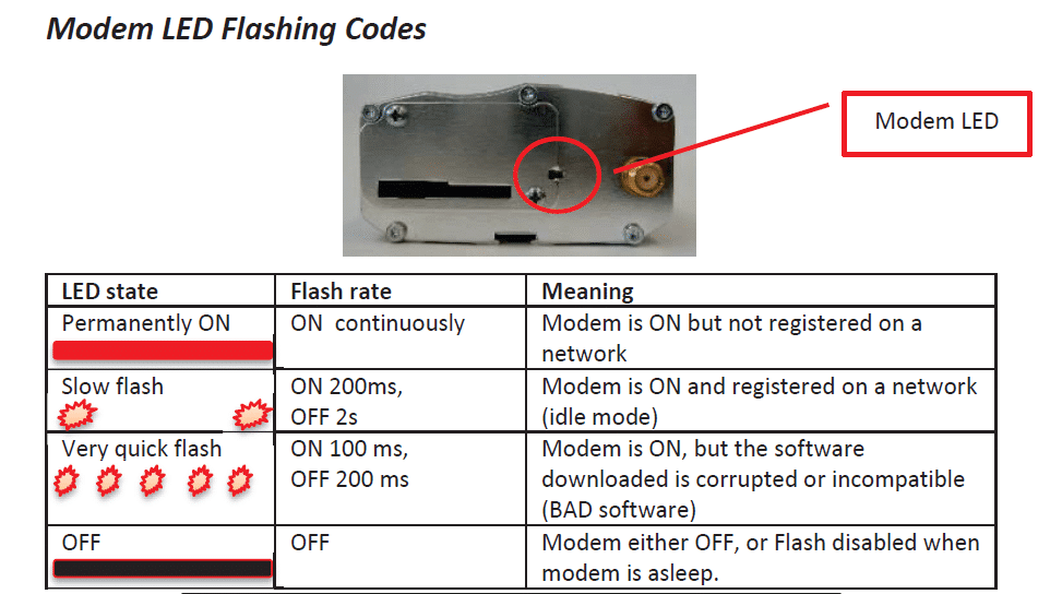
********It should be displaying a ‘slow flash’.********
2G/3G FX30 modem:
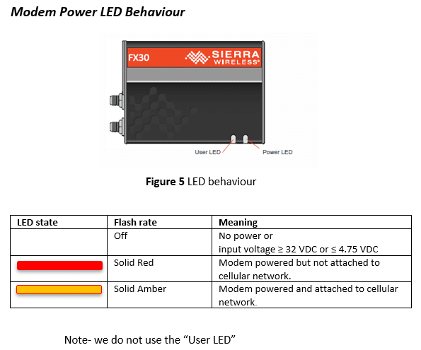
********It should be solid Amber********
- If the status LEDs (‘modem LED’ on 2G modem and ‘power LED’ on 2G/3G modem) indicate no power, check:
– The battery and power leads are connected to the modem.
– The solar charge regulator has green LEDs lit up on it (check wiring if LEDs are red)
– Check any fuses in the cable. - If the status LEDs show that the modem is not connected to a network, check the local network service – there may be a tower down. Also, check there is a SIM pushed into the modem SIM card slot, it should be ‘clicked’ into place and the cover latch is slid across on the 2G modem. For the 2G/3G FX30 modem, you may need to remove the cover plate.
- If the status LEDs are ok, log into DeltaLINK-Cloud and check the gateway status, it should connect within your sync time frame. It might be worth changing the sync rate to every 15minutes whilst it reconnects. This will increase the number of connections so you can check it more rapidly. Once the connection has re-established, the sync rate can be changed back to its previous setting.
- Always make sure that the same loggers are used with the same modem gateways before trying to connect. This will avoid any additional set up routines. If different loggers are used with different modems, then you’ll need to make sure that:
– The serial number for the logger has been entered correctly.
– The logger hasn’t already been registered on another user’s account – if it has, you’ll need to delete it from the other user’s account before registering it on your own account with the different modem gateway.
– Equally, make sure that you’re using your own modem gateways that are already registered to your account. If you are borrowing one from another user, you’ll need to ask them to delete the modem gateway from their account before registering it on your own account.
You can check the logger serial number by opening the lid and looking at the number printed on the circuit board inside. Alternatively, you can communicate with the logger using the DeltaLINK software on a laptop. The opening DeltaLINK screen shows the logger serial number in one of the information fields. - If there are any problems with the modem status LED or the connection cannot be resolved, please do get in touch with Delta-T technical support (tech.support@delta-t.co.uk).
-
-
Are there simple protocol commands to communicate with the Delta-T Devices Data loggers, so I can set up my own test software to communicate with them?
Question
Are there simple protocol commands to communicate with the Delta-T Devices Data loggers, so I can set up my own test software to communicate with them?
Answer
GP1, GP2 and DL6
The GP1/GP2 and DL6 loggers have a binary communications protocol, so it isn’t possible to use an ASCII terminal to communicate with them. We don’t publish the protocol because it’s highly optimized and complex, and it’s not practical for us to support development of custom implementations. Instead we provide a software development kit (SDK) for developing applications in Visual Studio, and a command line program for use in batch files for automating data retrieval.
- Using the development toolkit:
Instructions:
SDK instructions
Software can be found here:
link to software - Using a command line retrieval file to automatically retrieve a data file:
command line document link
DL2e
The DL2e does have a protocol for RS232 commands and the programmer’s guide can be found here:
DL2e programmer's guide - Using the development toolkit:
-
How do you insert large diameter cables (e.g. SPN1/BF5 cables) into the GP1/GP2/DL6 cable glands? – Video Guide
Question
How do you insert large diameter cables (e.g. SPN1/BF5 cables) into the GP1/DL6 cable glands? - Video Guide
Answer
The following video explains the best way that this can be done:
https://www.dropbox.com/s/lx9oyan70i75sgu/8%20way%20cable%20with%20sound.wmv?dl=0
Example in video is 8-way BF5 cable and GP1.
The GP2 logger has an optional expansion lid (GP2-G5-LID), which contains larger cable gland sizes to help with large diameter cables.
-
How do I set up my USB to RS232 convertor? – Photo Guide
Question
How do I set up my USB to RS232 convertor? - Photo Guide
Answer
- These convertors usually come with a website link to visit and download the drivers. Please make sure you download the drivers. Then follow all the on-screen instructions correctly.
- If you have purchased the device from Delta-T, you can download the drivers from here: https://www.dropbox.com/s/2pu0ll8b26y8qkm/CDM212364_Setup.exe?dl=0 or here: https://ftdichip.com/drivers/vcp-drivers/
- Once the drivers have been installed correctly, plug the USB convertor into a USB port on your PC.
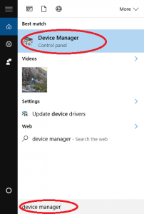
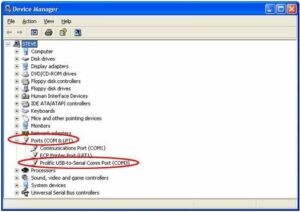
- The computer will then assign the convertor a COM port. You will need to check which com port has been assigned via the computer’s “device manager”:
Windows 10
Use the search tool in the bottom task bar to search for ‘device manager’:
Windows 8
Right click on Desktop background and select ‘All Apps’Right click on control panel and select ‘properties’:
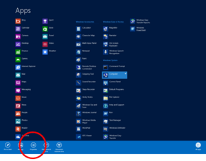
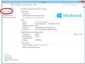
Click on Device Manager:
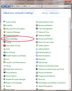
Windows 7
Click on Start, Control Panel, Device Manager:
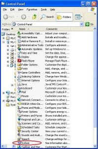
XP
Click on Start, Control Panel, System:
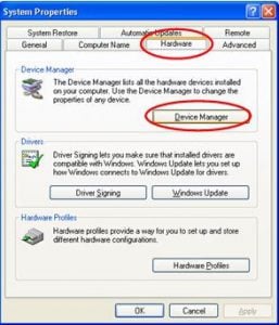
Under the ‘Hardware’ tab, click on ‘Device Manager’:
- Once in the device manager, expand the “ports” option. The example below shows a P.C which has the USB to serial converter installed (COM3):
- Please make sure that you use this same COM port number in the device software e.g. HH2read, SunRead, LS2win, DeltaLINK, AP4 retrieve.
- You will probably have to re-boot the P.C once the drivers have been installed.
- Also, please remember to use the original RS232 cable, that was supplied with your device, in series with the RS232 to USB converter.
Multiple USB convertor Installations check
If you have more than one USB to RS232 convertor installed, you can check which COM port has been assigned to the one you want to use, by doing the following:
- Unplug the USB convertor
- Open Device Manager > Ports (COM & LPT)
- Plug in the USB connector and observe which COM port is added to the list.
Technical Notes
-
Dual rate soil moisture recording with DeltaLINK 228 KBFilename: dual-rate-soil-moisture-recording-with-deltalink-v2-0
-
Example Use of Time of Day in the DeltaLINK 97 KBFilename: example-use-of-time-of-day-in-the-deltalink-v1-0
-
GP1 - measuring temperature differences using Pt100s 148 KB
The precision bridge adapter board (GP1-PBA1) enables the GP1 to record readings from bridge sensors, and from water-filled tensiometers in particular. This note explains how it can also be used to record temperature difference from a pair of Pt100 sensors.
Filename: gp1-measuring-temperature-differences-using-pt100s -
How the DeltaLINK Control Logic Works 152 KBFilename: how-the-deltalink-control-logic-works-v1-0
Tutorials
- GSM modem & network cabling for GP1 & DL6 - slide show 3 MB
Three slide show presentations about GP1 & DL6 system accessories: GSM Modem box, Network Cabling and an Example describing a flood and drain irrigation system using 32 GP1 loggers each controlling different irrigations zones, all networked up to one
DownloadFilename: gp1-and-dl6-gsm-modem-and-network-cabling-slide-show
Regulatory Information
- GP1 Logger EC Declaration of Conformity 56 KBDownloadFilename: gp1-logger-ec-declaration-of-conformity


