- Overview
- Specification
- Accessories
- Product Resources
- Advanced How to Buy
Testimonials
- Powerful and rugged field data logger
- SDI-12 enabled
- 12 differential channels
- Ideal for demanding research applications
- Compatible with DeltaLINK-Cloud online data sharing platform
- Calculation of full Penman-Monteith evapotranspiration equation
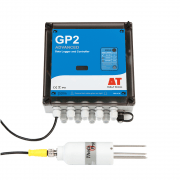
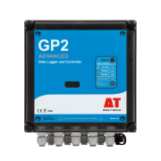
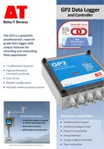
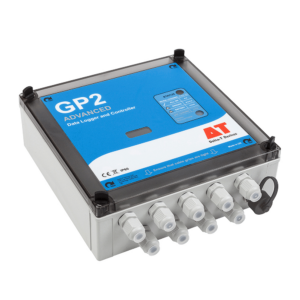
The GP2 is a powerful 12 channel data logger that is easy to use, versatile, rugged and reliable. It can log most sensor types and accepts voltage, resistance, current, potentiometer, bridge, counter, frequency, and digital state inputs. DeltaLINK software helps the user set up logging sequences and provides control over reading frequency, sensor type, thresholds, units and much more. All Delta-T sensors can be selected from a menu.
DeltaLINK–Cloud – online data viewing and sharing platform
GP2 Resource Centre
The Resource Centre contains a wide range of application information and tutorials – covering irrigation control, evapotranspiration, vapour pressure deficit, and much more. Visit the GP2 Resource Centre.
Power and flexibility
The GP2 Data Logger features advanced controller functionality, and sophisticated programs can be easily created via a simple scripting editor.
Click here to learn more about the advanced features of the GP2.
As the user’s needs change, the GP2 can adapt. An optional lid is available for additional cable entry points, or wider diameter cable entry points.
Building systems with the GP2 Data Logger
The GP2 is the ideal data logger for field work, with applications ranging from agronomy, meteorology and hydrology to eco-physiology and soil science. We can supply complete systems including sensors, enclosures, solar power and communications options.
The GP2 Data Logger is compatible with all Delta-T sensors. For the Delta-T WET Sensor there is a dedicated input channel.
Delta-T has decades of experience of instrumentation for environmental research and can advise on all aspects of system specification.
Sensors
The GP2 Data Logger can log most sensor types and accepts voltage, resistance, current, potentiometer, counter, frequency, and digital state inputs.
The GP2’s analog inputs can be fully customised. Each channel can have its own input type and recording parameters. DeltaLINK software gives the user control over reading frequency, thresholds and units, and provides statistical recording options for Average, Minimum, Maximum, Standard Deviation and more. Specialised wind options are available including wind rose, gusts and wind averaging.
Users can add their own custom sensor types to the sensor library, exploiting the GP2’s detailed configuration options. The GP2 provides 4 input ranges down to microvolt resolution with adaptive auto-ranging, excellent analog accuracy, and configurable sensor excitation – enabling it to support nearly all analog sensors.
Calculations based on the measurements from several input channels can be recorded and displayed as additional virtual channels (calculated measurements).
Ease of use
Simple point and click software makes it easy to configure channel set-up and recording intervals. The menus that support the advanced customisation options can be displayed or hidden as required.
Sensor connections are laid out logically with clear, easy-to-follow diagrams and notes.
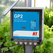
The GP2’s weatherproof case, battery power and convenient accessories make it very easy to install in the field – often without the need for a secondary enclosure.
Simulator
This unique software feature allows logging programs to be tested before real-world activation. For applications involving weather data, irrigation or soil moisture recording, the environmental variables can be changed to test how the program responds. Years of logging time can be simulated in just a few minutes.
Storage, communications and power
4 MB of FLASH memory enable storage of 2.5 million readings (typical). Data can be collected by a laptop locally via USB/RS232 or remotely using the cellular modem options.
The GP2 has 6 alkaline AA internal batteries as standard. An optional mains power adapter is available (type GP2-PSU). Up to 7 GP2s can share power and communications using an M12 cabling network. GP1 Data Loggers can be integrated into such a network via an adapter cable.
For external battery power options please enquire at sales@delta-t.co.uk
SDI-12 enabled
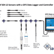
The GP2 Data Logger supports SDI-12 inputs as standard. GP2s supplied before March 2016 can be easily updated via a software download.
Key features:
- Huge additional input capacity for SDI-12 sensors
- Analogue and digital channels fully available
- Highly flexible logger + sensor networks
For more information visit our GP2 SDI-12 page.
Calculation of full ASCE/FAO 56 Penman-Monteith evapotranspiration equation
The GP2 Data Logger and DeltaLINK software (versions 3.7 and later), in combination with relevant sensors, enables the full ASCE/FAO-56 Penman-Monteith equation for calculating reference evapotranspiration (ETo).
ETo is calculated by the GP2 Data Logger using the available measurements of relative humidity, wind speed, solar radiation, and air temperature. This ET implementation includes the ability to vary crop albedo/LAI, canopy resistances, crop height and sensor heights.
The functionality can be easily accessed by users as a selectable recording option within DeltaLINK. Calculated ET can be recorded as hourly and daily values – and may be used in further bespoke calculations or to guide field irrigation decisions.
User guide to Penman-Monteith Evapotranspiration in the GP2 Logger.
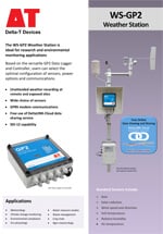
This enhancement also applies to the WS-GP2 Weather Station – an advanced research-grade system.
Applications
The GP2 Data Logger has a wide range of environmental, agricultural and industrial applications: Horticulture and Irrigation, Soil Science, Plant Physiology, Agronomy Climate Research and Meteorology, Agriculture, Turf and Gardens, Amenity Landscaping, Ecology, Field Trials, Eco-Physiology.
Specification
| Input connections | 12 differential (or 24 single-ended) analog inputs configurable as: Voltage, Resistance (12 3-wire or 24 2-wire), Bridge (12), Potentiometer (12) 4 digital inputs as: Counters, (2 fast + 2 slow), Frequency, Digital state 1 Delta-T WET sensor channel Unlimited virtual channels Serial input channel: 62 SDI-12 sensors or a single WET Sensor |
| Control outputs | 2 relay outputs expandable to 6 (1 A) |
| Readings stored | 2.5 Million |
| Recording rate | 1 second to >24 hours |
| Configuration | DeltaLINK |
| Communication options | SDI-12, USB, RS232, ethernet or modem |
| Sensor excitation | Calibrated 3 V reference, +5 V and +12 V regulated, or 5 to 10.5 V (battery or external power), user selectable |
| Power | 6 AA alkaline batteries or external power 10-15 V DC |
| Battery life (dependent on usage) | >310K readings, lasting 530 days |
| Enclosure rating | IP65 |
| Temperature range | -20 to +60°C |
| Display | – |
| Size | 225 x 185 x 75 mm |
| Typical applications | Demanding research projects |
| Environmental monitoring | |
| Varied control applications |
| Sensor compatibility (maximum number of sensors that could be connected [1] | |
| WET150 | ✓ (62) |
| ML3 | ✓ (6) with temp / (12) without temp |
| SM150T | ✓(6) with temp / (12) without temp |
| PR2 | ✓(2 PR2/6) (3 PR2/4) |
| PR2 SDI-12 | ✓ (50) PR2/6 ✓ (62) PR2/4 |
| WET Sensor | ✓ (1) |
| EQ3 | ✓ 6 with temp / 12 without temp |
| Temperature | ✓ (12) |
| Tensiometers | ✓ (12) |
| Counters or Events | ✓ (4) 2 fast 2 slow |
| Relay Output | ✓(2) expandable to (6) |
Accessories
Hardware
Main components and software
Mountings and enclosures
- Battery Box – up to 120AH
- DL-MKT Mounting Plate for GP2, GP1 OR DL6 Logger
- WS-CAN – GP2 and DL2e Logger Canopy
- M2-MIN-FSG 2m mast, excluding logger canopy
- M2-FSG 2m mast, excluding logger canopy
- M2-FSG 2m mast for GP2 Logger
- M2 BASE Base socket for M2-FSG, M2-MIN-FSG or S-POLE
- M-ENCL-B2 – Enclosure and 12 V wiring kit for GP2
Installation accessories
Cables and networks
Remote communications
Spares and consumables
Power options
Other
Product Resources
Data Sheets
- GP2 Data Logger and Controller Data Sheet 4 MB
- DeltaLINK-Cloud - online data viewing and sharing service 2 MB
- GP2 Data Logger cabling and network options 1 MB
- WS-GP2 Weather Station Data Sheet 612 KB
- Environmental and Meteorological Sensor Specifications 5 MB
Case Studies
-
GP2 Data Logger Case Study - CEPHaS 2018 3 MB
The use of GP2 in studying how conservation agriculture practices affect the behavior of water in soil, crop and groundwork systems.
Filename: GP2_Data_Logger_Case_Study_CEPHaS_2018 -
Implementation and evaluation of a slope stability equation performed with the DeltaLINK simulator 1 MBFilename: Safety_Factor poster_04.11.13_download
-
An Instrumented Rhizotron to Investigate the Root Growth In Wheat 2 MBFilename: Rhizotron-to-investigate-the-root-growth-in-wheat-ver-1.0-download
-
Newcastle University uses the GP2 for urban water sustainability solutions research. 852 KB
An explanation of how the National Green Infrastructure Facility at Newcastle University uses the GP2 in integrated urban water sustainability solutions research.
Filename: Case_study_Newcastle_Urban_obervatory_SuDs_project_v2 -
Cranfield University - Using GP2 to improve banana irrigation management in ColombiaFilename: →
-
NIAB East Malling Research - precision irrigation research with the GP2 631 KB
NIAB EMR have used the GP2 Data Logger extensively in several precision Irrigation research projects and commercial crop trials.
Filename: GP2_EMR_Case_Study_v.1 -
Research institute uses the GP2 to investigate the effects of protective covering on fruit cultivation 2 MB
The Kompetenzzentrum Obstbau-Bodensee Institute in Germany uses the GP2 logger to Investigate the protective effect of covering systems on soft fruit cultivation.
Filename: GP2_case_study_monitoring_protected_evironments_ver_08_02_21 -
GP2 Data Logger and sensors used by Rothamsted Research for major experiment 3 MBFilename: Case_Study_Delta-T_Rothamsted_2021
-
Seven brief Delta-T Devices soil moisture measurement case studiesFilename: →
-
BBRO use GP2 Logger & WET150 to tackle drought risk in sugar beet 548 KBFilename: SOL4-KIT-UM-1.4
Software
Videos
Manuals
- GP2 Data Logger User Manual v 3.2Filename: →
- 3G Modem Gateway User Manual v1.2 2 MBFilename: 3G_Modem_Gateway_User_Manual_v1.2
- M Enclosure for GP2 User Manual 3 MBFilename: m-encl-b2-um-5-0
- WS-GP2 Quick Start Guide v2.4 2 MBFilename: WS-GP2 Quick Start Guide v2.4
FAQs
-
Setting up an M12 cable network to ensure a waterproof and secure connection.
Question
What is the best practice for setting up a M12 cable network to ensure a waterproof and secure connection..
Answer
It applies to:
GP2 for SDI-12 and logger networks.
Celora for SDI-12 networks.
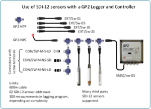
All sensors with M12 connector cables.Examples of SDI-12 network and GP2 logger networks:
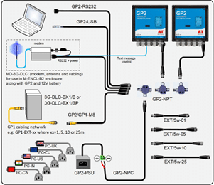
DO
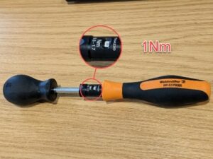
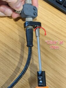
When connecting multiple cables and T-piece together, it is essential that any M12 connector is tightened sufficiently:• Ensure internal connector O-ring and opposite sealing face are free from dirt.• Tighten the connector thumbscrews as much as you can by hand or use a torque driver set to 1Nm to be sure. See video:
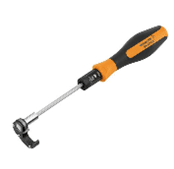
We recommend the Weidmuller ‚”1900021000″ torque driver:
• This will save lots of painstaking troubleshooting hours if you do have a loose connection and give you piece of mind that all connectors are correctly tightened.
• Untightened connectors can come undone and let water into the cable network which can damage wire cores and cause erroneous readings.
Connect in the office first and then transfer the network to the field. This way, you’re not trying to do it in unpleasant weather and the time pressures are off.
DON’T
Use duct tape. This will hold water against the connector. If tightened correctly, the connector will seal and hold. -
What checks are needed when setting up a DeltaLINK-Cloud modem gateway after a period of storage?
Question
What checks are needed when setting up a DeltaLINK-Cloud modem gateway after a period of storage?
Answer
You may choose to shut down your DeltaLINK-Cloud modem once the growing season is over (e.g. Winter). When setting up the equipment again for the next growing season, it’s important to perform a few checks, just to make sure everything is working ok.
-
- Re-charge the 12v battery before redeploying otherwise the modem won’t have any power to start up. If you need a battery charger for the LBAT4 battery, please contact sales@delta-t.co.uk.
- Make sure the aerial/antenna is connected securely and is mounted as high as possible.
- Make sure all loggers are connected to the modem box/kit. Check the cables for any damage that may have occurred during storage. If replacement cables are needed, please contact sales@delta-t.co.uk.
- Connect the 12v battery to the power leads in the modem box or, if you are using the kit in a steel enclosure, make sure the battery is connected directly into the logger power terminals and the modem is connected to the logger using the 5-way M12 connector.
- Check the modem status LED (note, the modem may take a few minutes to connect to the network and display the correct LED flashing code):
2G FX009 modem:
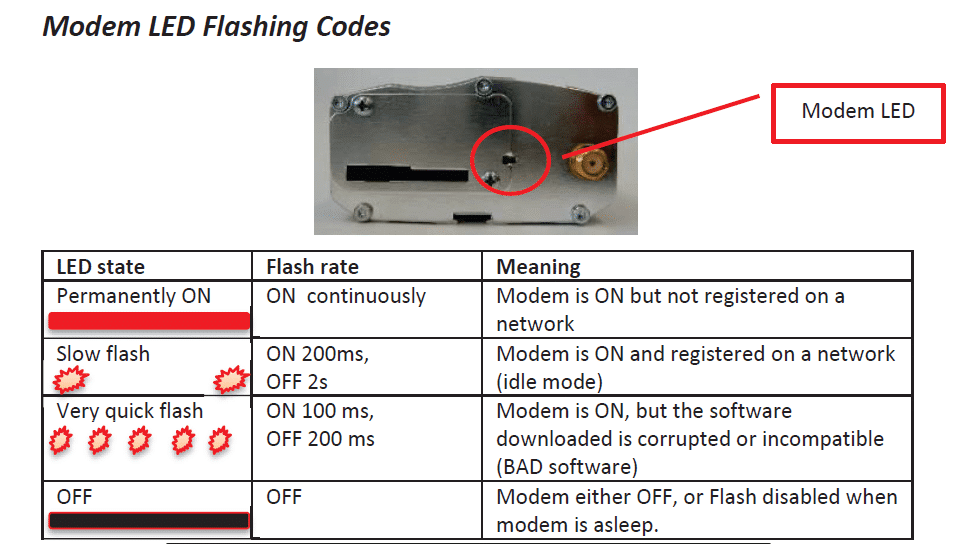
********It should be displaying a ‘slow flash’.********
2G/3G FX30 modem:
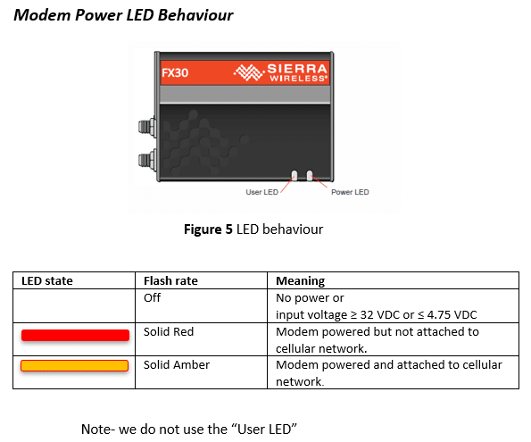
********It should be solid Amber********
- If the status LEDs (‘modem LED’ on 2G modem and ‘power LED’ on 2G/3G modem) indicate no power, check:
– The battery and power leads are connected to the modem.
– The solar charge regulator has green LEDs lit up on it (check wiring if LEDs are red)
– Check any fuses in the cable. - If the status LEDs show that the modem is not connected to a network, check the local network service – there may be a tower down. Also, check there is a SIM pushed into the modem SIM card slot, it should be ‘clicked’ into place and the cover latch is slid across on the 2G modem. For the 2G/3G FX30 modem, you may need to remove the cover plate.
- If the status LEDs are ok, log into DeltaLINK-Cloud and check the gateway status, it should connect within your sync time frame. It might be worth changing the sync rate to every 15minutes whilst it reconnects. This will increase the number of connections so you can check it more rapidly. Once the connection has re-established, the sync rate can be changed back to its previous setting.
- Always make sure that the same loggers are used with the same modem gateways before trying to connect. This will avoid any additional set up routines. If different loggers are used with different modems, then you’ll need to make sure that:
– The serial number for the logger has been entered correctly.
– The logger hasn’t already been registered on another user’s account – if it has, you’ll need to delete it from the other user’s account before registering it on your own account with the different modem gateway.
– Equally, make sure that you’re using your own modem gateways that are already registered to your account. If you are borrowing one from another user, you’ll need to ask them to delete the modem gateway from their account before registering it on your own account.
You can check the logger serial number by opening the lid and looking at the number printed on the circuit board inside. Alternatively, you can communicate with the logger using the DeltaLINK software on a laptop. The opening DeltaLINK screen shows the logger serial number in one of the information fields. - If there are any problems with the modem status LED or the connection cannot be resolved, please do get in touch with Delta-T technical support (tech.support@delta-t.co.uk).
-
-
Are there simple protocol commands to communicate with the Delta-T Devices Data loggers, so I can set up my own test software to communicate with them?
Question
Are there simple protocol commands to communicate with the Delta-T Devices Data loggers, so I can set up my own test software to communicate with them?
Answer
GP1, GP2 and DL6
The GP1/GP2 and DL6 loggers have a binary communications protocol, so it isn’t possible to use an ASCII terminal to communicate with them. We don’t publish the protocol because it’s highly optimized and complex, and it’s not practical for us to support development of custom implementations. Instead we provide a software development kit (SDK) for developing applications in Visual Studio, and a command line program for use in batch files for automating data retrieval.
- Using the development toolkit:
Instructions:
SDK instructions
Software can be found here:
link to software - Using a command line retrieval file to automatically retrieve a data file:
command line document link
DL2e
The DL2e does have a protocol for RS232 commands and the programmer’s guide can be found here:
DL2e programmer's guide - Using the development toolkit:
-
How do I set up my USB to RS232 convertor? – Photo Guide
Question
How do I set up my USB to RS232 convertor? - Photo Guide
Answer
- These convertors usually come with a website link to visit and download the drivers. Please make sure you download the drivers. Then follow all the on-screen instructions correctly.
- If you have purchased the device from Delta-T, you can download the drivers from here: https://www.dropbox.com/s/2pu0ll8b26y8qkm/CDM212364_Setup.exe?dl=0 or here: https://ftdichip.com/drivers/vcp-drivers/
- Once the drivers have been installed correctly, plug the USB convertor into a USB port on your PC.
- The computer will then assign the convertor a COM port. You will need to check which com port has been assigned via the computer’s “device manager”:
Windows 10
Use the search tool in the bottom task bar to search for ‘device manager’:

Windows 8
Right click on Desktop background and select ‘All Apps’Right click on control panel and select ‘properties’:

Click on Device Manager:

Windows 7
Click on Start, Control Panel, Device Manager:

XP
Click on Start, Control Panel, System:

Under the ‘Hardware’ tab, click on ‘Device Manager’:

- Once in the device manager, expand the “ports” option. The example below shows a P.C which has the USB to serial converter installed (COM3):

- Please make sure that you use this same COM port number in the device software e.g. HH2read, SunRead, LS2win, DeltaLINK, AP4 retrieve.
- You will probably have to re-boot the P.C once the drivers have been installed.
- Also, please remember to use the original RS232 cable, that was supplied with your device, in series with the RS232 to USB converter.
Multiple USB convertor Installations check
If you have more than one USB to RS232 convertor installed, you can check which COM port has been assigned to the one you want to use, by doing the following:
- Unplug the USB convertor
- Open Device Manager > Ports (COM & LPT)
- Plug in the USB connector and observe which COM port is added to the list.
Technical Notes
-
User guide to Penman Monteith Evapotranspiration in the GP2 Data logger and controller 876 KBFilename: User_guide_to _Penman Monteith_ Evapotranspiration_in_the GP2_Data_logger
-
A method of calibration and variance analysis with respect to the Penman-Monteith equation for the Turc, Hargreaves and Abtew potential evapotranspiration models 1 MB
The full ASCE/FAO-56 Penman-Monteith evapotranspiration (PM-ET) equation and crop coefficients are often employed for irrigation scheduling of open-field crops. This paper focuses on the Turc, Hargreaves and Abtew models which employ daily averages of: solar radiation, air temperature and relative humid to determine daily ET.
Filename: Calibration and variance analysis with respect to Penman-Monteith equation for potential evapotranspiration models 5.8.19
Advanced features of the new GP2 Data Logger and Controller
- Powerful, yet highly accessible Script Editor
- Virtual Channels
- Unique Simulator function
- Smart irrigation and fertigation
- PID control
- Model implementation, simulation and evaluation
- Evapotranspiration calculation and analysis
Customised control (simple or advanced)
Control conditions for experiments and applications can range from simple thresholding to sophisticated calculations using the Script Editor. Control parameters (e.g. target soil moisture level) can be adjusted without interrupting data logging.
Script Editor
The GP2 is a flexible and powerful research and control instrument – enabling model implementation, simulation and evaluation. The new Script Editor is easy to use, yet allows the creation of complex functions such as disease prediction, degree days, dew point, wind chill factor, PID control, and evapotranspiration calculation and analysis.
- Script Editor creates sequences of operations to implement models
- Advanced control and recording capabilities
- Easy user interface: no typing out of commands; no programming language
- Implement simple or complex conditions, algebraic expressions and record result values
- Create and manipulate variables e.g. for disease risk factor
This powerful software feature creates step by step operations to control simple or complex processes or recording requirements. The editor interface is easy to use – no programming language is involved. It can also implement models, useful in areas such as disease prediction or multi-zone irrigation. This degree of sophistication, including the ability to apply PID control, means the potential applications are numerous and varied.
Virtual channels
Calculations based on the measurements from several input channels can be recorded and displayed as additional “virtual channels”.
Simulator
- Test and optimise logging programs using the built-in Simulator.
- Simulate how the program responds to changes in weather data, irrigation systems and soil moisture movement etc.
This unique software feature allows logging programs to be tested before real-world activation. For applications involving weather data, irrigation or soil moisture recording, the environmental variables can be changed to test how the program responds. Years of logging time can be simulated in just a few minutes.
Typical examples of advanced control and modelling
PID Control – The GP2 is a powerful research tool for experimental research. The powerful new Script Editorfunction gives the user an accessible way to create sophisticated mathematical functions and models that can be applied in real-time to the measurement data collected by the GP2. In experimental work detailed here we have created an enhanced PID controller within the DeltaLINK 3.0 Script Editor – enabling the GP2 to deliver precision irrigation control for a Poinsettia plant. The data collected shows precise control of soil moisture levels and the PID controller responding appropriately to the diurnal cycle. The experimental system also includes water flow and radiation sensors. The GP2 collects data from these sensors and calculates daily totals enabling the relationship between solar radiation and water use to be investigated.
Download GP2 PID scientific poster here.
Explanation of PID Control
(With reference to information below, please note that, as of Sept 2018, the GP2 now also calculates the full FAO 56 / ASCE Penman Monteith equation – see GP2 overview page for more details.)
Evapotranspiration calculation and analysis In this example, the GP2’s Script Editor & Simulator features were used for a comparison of four empirical potential evapotranspiration equations (PET). The Script Editor was used to implement mathematical models (Xu & Singh 2001) that calculated daily average values for air temperature, relative humidity, and solar radiation. These values were then used with empirical models to estimate PET. The results indicate that the solar radiation based models are well grouped and follow a similar trend, whereas the temperature based model (McCloud) appears to overestimate PET.
The empirical PET models described in the poster can be installed into a standard GP2, and with the appropriate sensors, used to calculate real-time estimates of PET. If comparison pan evaporation or lysimeter data is available then the model coefficients can be adjusted on the GP2 to optimise the model for local conditions as outlined by Xu & Singh (2001).
Download GP2 Evapotranspiration scientific poster here.


